Piping Drawings
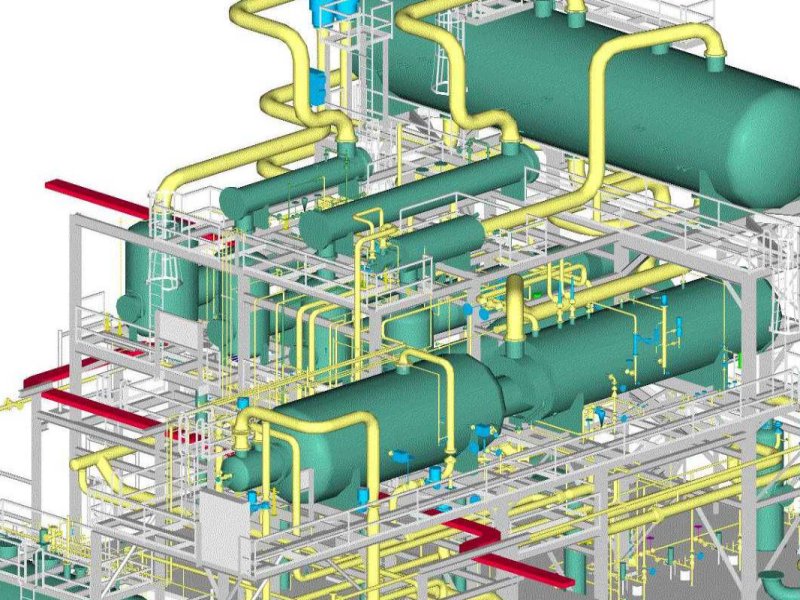
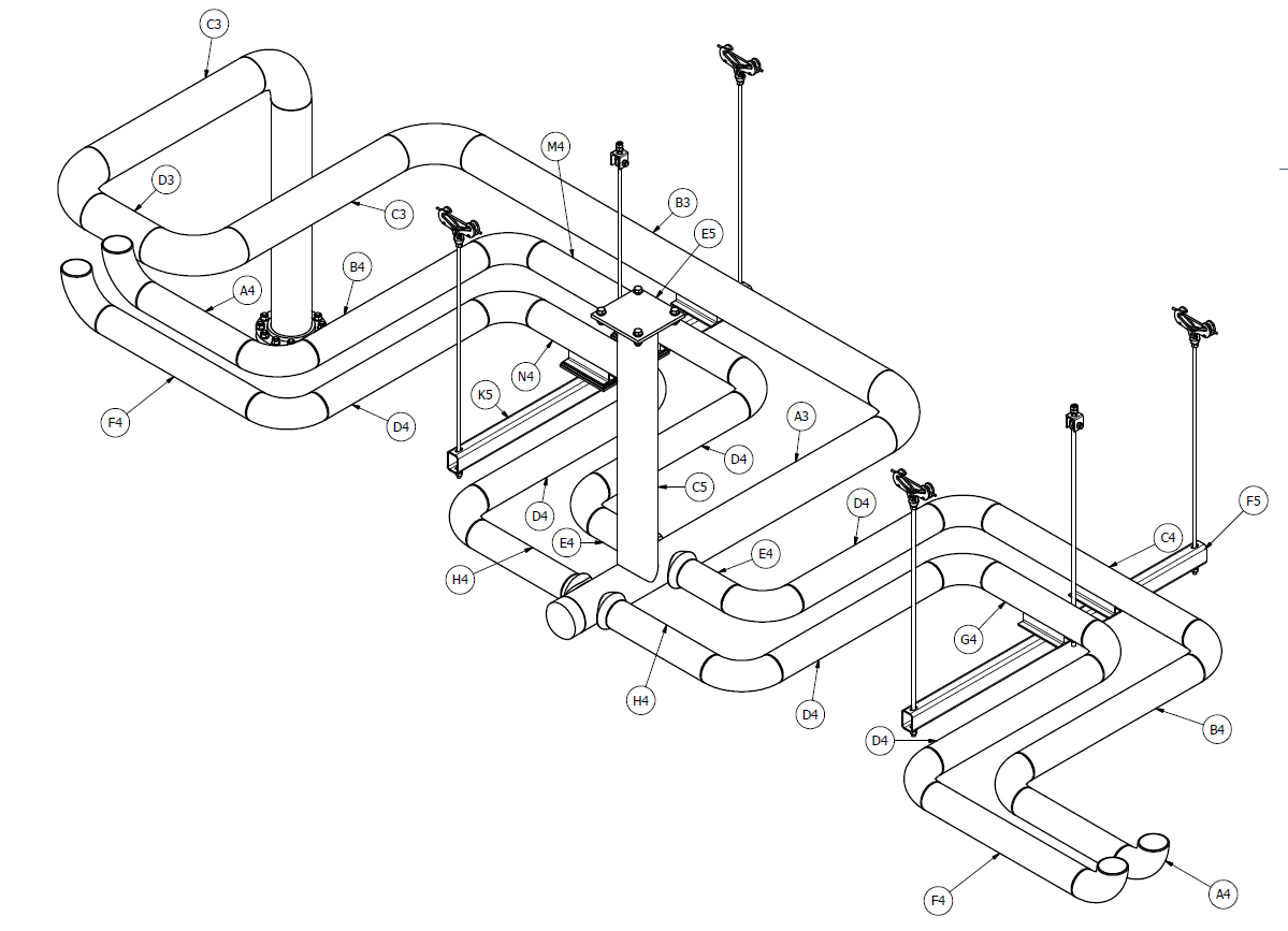
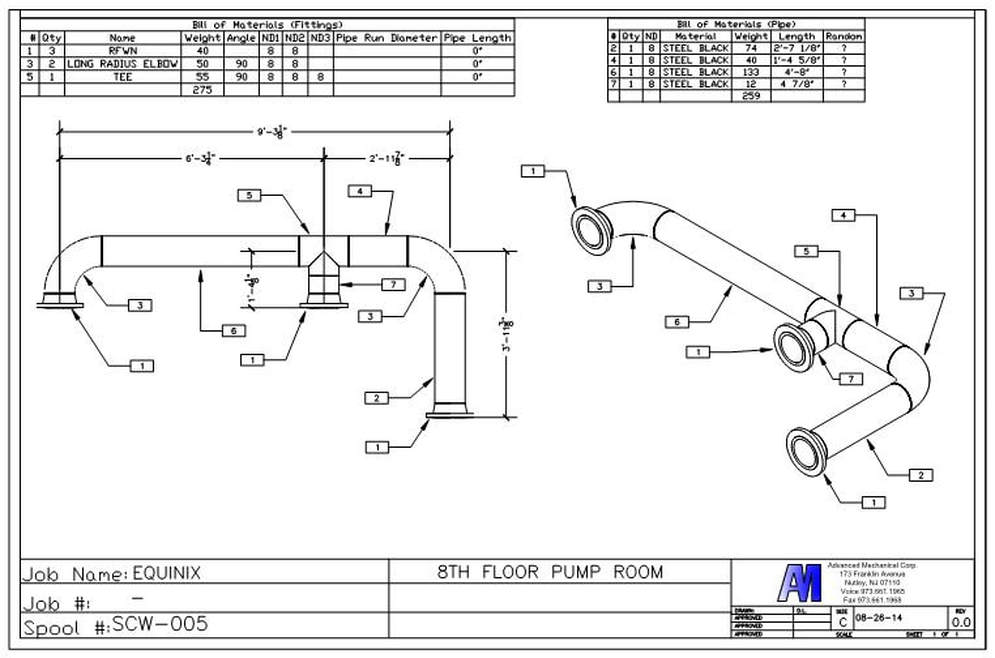
Piping Drawings - Second, draw the pipeline with the help of simple lines. Types of drawings •process flow diagrams: Web piping isometric drawing consists of three sections. Draw the route of the pipeline. • charts such as line spacing within racks. General arrangement drawing (gad) or piping plan drawing; For designing processes or power piping, mostly five types of piping drawings are developed. Web piping drawings are indispensable tools for engineers and designers involved in the planning, fabrication, installation, and maintenance of piping systems. These drawings provide valuable information about the pipeline's layout, dimensions, materials, and inspection points. Web piping and instrumentation diagrams (p&ids) use specific symbols to show the connectivity of equipment, sensors, and valves in a control system. The isometric is the end product and must contain all the information necessary to purchase the correct material, fabricate the piping configuration, and. There are different types of piping diagrams and they are process flow diagrams, piping and instrumentation diagram, orthographic pipe drawing, piping isometrics, and block flow diagrams. Each type of drawing serves a specific purpose and provides valuable. How it works •layout drawings: Web piping isometrics, commonly referred to as isos, are encountered nowadays throughout all process industries such as oil & gas, chemical, pharmaceutical, or food industries. What a process does •piping & instrument diagrams: For designing processes or power piping, mostly five types of piping drawings are developed. Piping plan drawings/general arrangement drawings (gad). Web drawings are engineering’s international language engineers all over the world can understand them. How to read iso drawings. Review drawings and data from piping valves and specialized suppliers. Draw the route of the pipeline. Web creating piping isometric drawings involves the use of various tools and software, both traditional and digital. Unlike orthographic drawings that show different views (front, side, and top) separately, isometric drawings combine these views into a single, easily understandable image. Some officials were alarmed after examining classified intelligence on wednesday and warned of ominous consequences; The drawing sheet sizes shall be any of the following. Process flow diagram (pfd) plant and instrumentation diagram (p&id) plot plan; Web. First create a drawing sheet in din a4 or a3 and activate the isometric grid. Web create the piping isometric drawing manually 1. Draw the route of the pipeline. When using software, it is. These symbols can represent actuators, sensors, and controllers and may be. Web the types of piping drawing required are as follows: Web easy isometric is the first pipe isometric drawing app that helps users make detailed isometric drawings in the field and without the need for tedious reference materials. Each type of drawing serves a specific purpose and provides valuable information to different stakeholders throughout the project lifecycle. Types of drawings. In isometric drawings, pipes are represented as lines. Web types of pipeline drawings. 14, 2024 updated 7:32 p.m. How to read iso drawings. The instructor explains the state of art in mechanical & piping drafting. Web • drawing standards such as layering, text heights, and drawing symbols. Web a piping isometric drawing is a technical illustration that presents a 3d representation of a piping system. General arrangement drawing (gad) or piping plan drawing; By understanding the different types of. Web piping isometric drawing consists of three sections. Web we are concluding our first pipefitter series run with a video on how to draw isometric drawings. Weld joint type and its location; Automated bill of materials no more tedious material tracking when creating a pipe isometric drawing. Web piping isometric drawing consists of three sections. Coordinate and liaise with lead engineers of the disciplines to ensure smooth flow. Web easy isometric is the first pipe isometric drawing app that helps users make detailed isometric drawings in the field and without the need for tedious reference materials. Web types of piping drawings (pdf) types of piping drawings. These engineering drawings are used worldwide in industrial plant design, construction, commissioning, operation, and maintenance. Coordinate and liaise with lead engineers of. 14, 2024 updated 7:32 p.m. How it works •layout drawings: All components are represented using various p&id symbols. Create a drawing sheet for isometrics. The piping plan drawing (or the 3d model) is important but it is just a means to an end. Web piping isometrics, commonly referred to as isos, are encountered nowadays throughout all process industries such as oil & gas, chemical, pharmaceutical, or food industries. The drawing sheet sizes shall be any of the following. Web the types of piping drawing required are as follows: Web piping drawings are indispensable tools for engineers and designers involved in the planning, fabrication, installation, and maintenance of piping systems. These engineering drawings are used worldwide in industrial plant design, construction, commissioning, operation, and maintenance. Web a p&id or process and instrumentation diagram provides a detailed graphical representation of the actual process system that includes the piping, equipment, valves, instrumentation, and other process components in the system. These symbols can represent actuators, sensors, and controllers and may be. By understanding the different types of. They provide clear information on the. Web we are concluding our first pipefitter series run with a video on how to draw isometric drawings. This perspective provides a clear visualization of how pipes.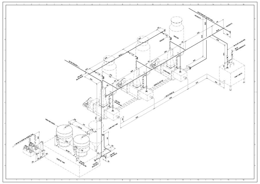
How to draw isometric drawing of piping hondate

Piping Design Basics Piping Isometric Drawings Piping Isometrics

How to read isometric drawing piping dadver

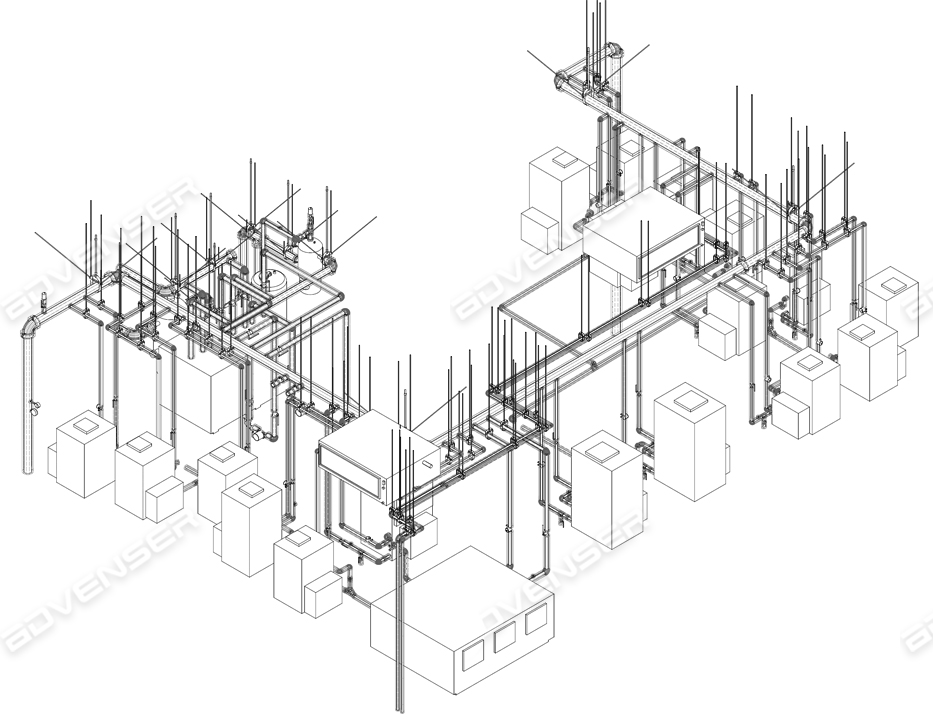
Isometric Piping Drawings Advenser
Piping Drawing at GetDrawings Free download

How to read piping Isometric drawing YouTube
Piping Drawing at GetDrawings Free download
PIPING DRAWINGS

How to read piping isometric drawing, Pipe fitter training, Watch the
Isometric Piping Drawings Advenser
General Arrangement Drawing (Gad) Or Piping Plan Drawing;
Web Coordinate Review Of Supplier Drawings And Data Used For The Project.
This Section Explores The Available Options And Their Characteristics:
• Charts Such As Line Spacing Within Racks.
Related Post: