Piping Drawing
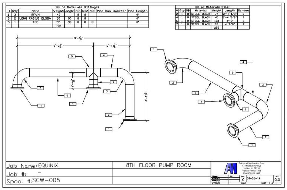
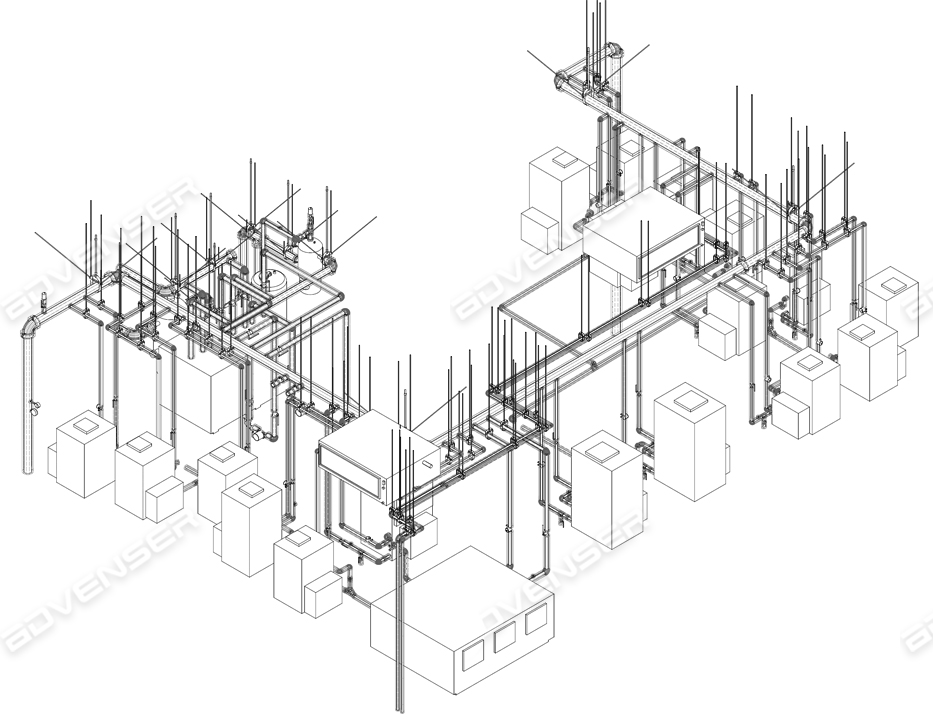
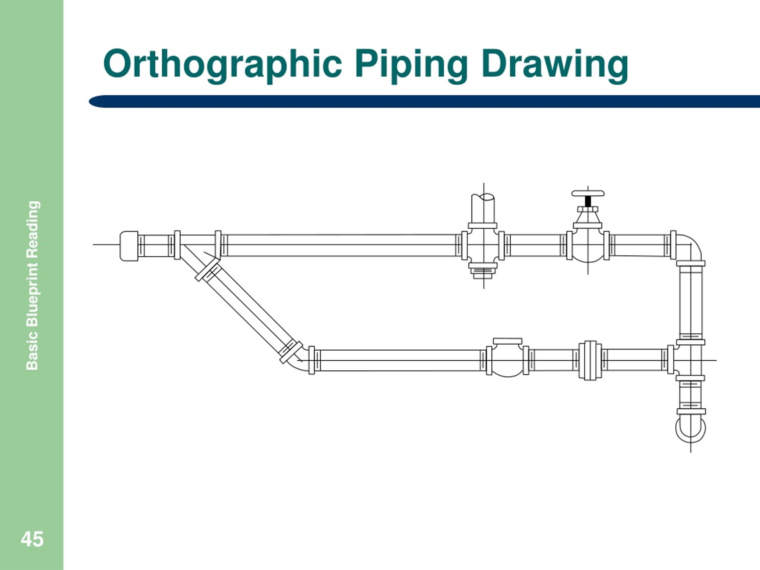
Piping Drawing - Web of drafting abbreviations used on piping drawings. Draw the route of the pipeline. Web we are concluding our first pipefitter series run with a video on how to draw isometric drawings. These drawings are developed from the schematics and specifications for process piping prepared by the process engineer. Ensuring clarity and readability of the final isometric drawing. Web fabrication, construction, and architectural drawings. Reading and interpreting piping isometric drawings Each client mandates the drawing numbering to be used. Web easy isometric is the first pipe isometric drawing app that helps users make detailed isometric drawings in the field and without the need for tedious reference materials. Web the easiest way to visualize your piping process and instrumentation by using our professional piping design software. Web one person referred to it as “a new russian space threat capability.”. File numbering, which ideally should equate to table 1.2 branch connections instrument and utility air Process flow diagram (pfd) plant and instrumentation diagram (p&id) plot plan; Ensuring clarity and readability of the final isometric drawing. This is a certified workshop! Reading and interpreting piping isometric drawings Web our comprehensive guide to learn what to look for — and what to avoid — when you’re in the market for piping design software. General arrangement drawing (gad) or piping plan drawing; Second, draw the pipeline with the help of simple lines. First create a drawing sheet in din a4 or a3 and. Draw the route of the pipeline. No more tedious material tracking when creating a pipe isometric drawing. Piping and instrument drawings (p&ids) p&ids are usually designed to present functional information about a system or component. Web types of piping drawings (pdf) types of piping drawings. Web dimensioning the drawing to specify pipe lengths, diameters, and angles. P&ids are used to develop guidelines and standards for facility operation. Web methods of representing piping systems. Web piping isometric drawing dimensions are always from center to center of pipe. Web one person referred to it as “a new russian space threat capability.”. The drawing sheet sizes shall be any of the following. P&id symbols exist for all major components and. Web features of piping isometric drawing it is not drawn to the scale, but it is proportionate with the exact dimensions represented. Web piping isometric drawing dimensions are always from center to center of pipe. Web methods of representing piping systems. 14, 2024 updated 7:32 p.m. Material description for pipe is described in piping isoemtric drawing on top right corner. Web how to read piping isometric drawing symbols. P&ids are used to develop guidelines and standards for facility operation. Brief on ga drawing/piping plan drawing/piping layout drawing Web we are concluding our first pipefitter series run with a video on how to draw isometric drawings. Web we are concluding our first pipefitter series run with a video on how to draw isometric drawings. Web learn to read a piping isometric drawing and learn how to fabricate a pipe spool. The instructor explains the state o. Web create the piping isometric drawing manually 1. Ensuring clarity and readability of the final isometric drawing. The piping plan or general arrangement drawings (fig. P&ids are used to develop guidelines and standards for facility operation. Web types of piping drawings (pdf) types of piping drawings. Brief on ga drawing/piping plan drawing/piping layout drawing These symbols can represent actuators, sensors, and controllers and may be apparent in most, if not all, system diagrams. File numbering, which ideally should equate to table 1.2 branch connections instrument and utility air Web types of piping drawings (pdf) types of piping drawings. Web p&id is the acronym for “piping and instrumentation diagram”, i.e. A very detailed diagram showing the processes happening within a plant, the involved equipment, and their interconnections. Some officials were alarmed after examining classified. Web a piping single line drawing (or piping one line drawing) is a piping drawing that shows the size and location of pipes, fittings and valves. Web material, pipe culvert'', the quantity to be paid shall be the number of cubic meter completed in place and accepted, measured in final position between limits as follows: Web how to read piping. These drawings are developed from the schematics and specifications for process piping prepared by the process engineer. There are different types of piping diagrams and they are process flow diagrams, piping and instrumentation diagram, orthographic pipe drawing, piping isometrics, and block flow diagrams. How to read iso drawings. Web how to read piping isometric drawing symbols. Create a drawing sheet for isometrics. Web methods of representing piping systems. Some officials were alarmed after examining classified intelligence on wednesday and warned of ominous consequences; P&ids are used to develop guidelines and standards for facility operation. Material description for pipe is described in piping isoemtric drawing on top right corner. A very detailed diagram showing the processes happening within a plant, the involved equipment, and their interconnections. The instructor explains the state o. Piping and instrument drawings (p&ids) p&ids are usually designed to present functional information about a system or component. Web create the piping isometric drawing manually 1. See our picks for the best piping design software, including paid and free options and the key. Web a piping single line drawing (or piping one line drawing) is a piping drawing that shows the size and location of pipes, fittings and valves. Web the piping and instrumentation diagram provides a basis for maintenance and modification works.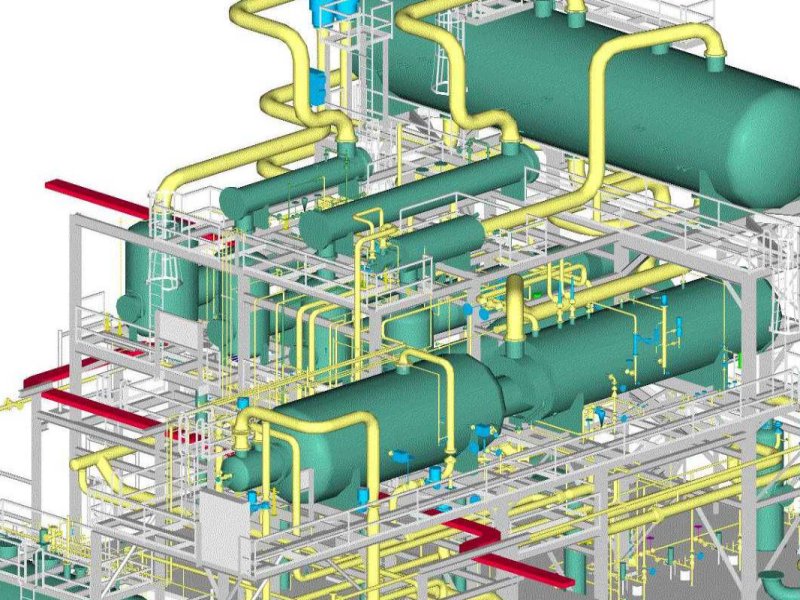
Piping Drawing at GetDrawings Free download
What Is Piping Plan Drawing Design Talk
Sample Iso Piping Drawing

Piping Design Basics Piping Isometric Drawings Piping Isometrics

How to read piping isometric drawing, Pipe fitter training, Watch the
Piping orthographic drawing symbols kloology

Piping drawing and symbols

Isometric Piping Drawings Advenser

How to read isometric drawing piping dadver

How to read piping Isometric drawing YouTube
Web Types Of Piping Drawings (Pdf) Types Of Piping Drawings.
Web Piping And Instrumentation Diagrams (P&Ids) Use Specific Symbols To Show The Connectivity Of Equipment, Sensors, And Valves In A Control System.
P&Ids Provide More Detail Than A Process Flow Diagram With The Exception Of.
Web Of Drafting Abbreviations Used On Piping Drawings.
Related Post: