Isometric Drawing Piping Symbols
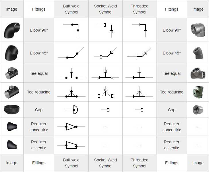
Isometric Drawing Piping Symbols - Various symbols are used to indicate piping components, instrumentation, equipments in engineering drawings such as piping and instrumentation diagram (p&id), isometric drawings, plot plan, equipment layout, welding drawings etc. Any instrument attached to a piping system can. Web isometric drawing techniques to increase drawing efficiency: Accurate drawing symbols, callouts, precise coordinates, and elevations provide intricate information to the fabricator. Piping iso symbols and meaning. In the interview, the client can ask you, by counting the material in it, show which material is used in so many pieces. Web isometric piping drawings are not scale drawings; Web type of piping components: Create a prototype for isometric drawings? They are not realistic, pipes are shown as single lines, and symbols are used to represent pipe fittings, valves, pipe gradients, welds, etc. Various symbols are used to indicate piping components, instrumentation, equipments in engineering drawings such as piping and instrumentation diagram (p&id), isometric drawings, plot plan, equipment layout, welding drawings etc. Lighter lines show connected pipe, and are not parts of the symbols. Web piping symbols are a quick reference to know about the type of fitting and component to be used.. Any instrument attached to a piping system can. Web no, piping isometric drawings are prepared using a specialised isometric projection in which all piping components are shown using standard symbols, and all pipes are shown as simple lines. Valves, fittings, instruments, equipment… common drawing components Web piping isometric drawing symbols for various markings. Web the process of drafting isometric drawings. Isometric drawing piping symbols serve as a ready reference for the type of fittings and components. Web piping isometric drawing symbols for various markings. Isometric symbols for fittings, flanges, and. Web piping symbols serve as the alphabet of isometric drawings, with each symbol representing a specific component, similar to words in a language. Web isometric symbols for piping fittings. Unlike orthographics, piping isometrics allow the pipe to be drawn in a manner by which the length, width and depth are shown in a single view. Web the process of drafting isometric drawings for a pipeline system involves referencing the arrangements of the pipelines, sections, and elevation drawings during its development. Web symbols for piping and instrumentation diagrams (pid). Web. Any instrument attached to a piping system can. Various symbols are used to indicate piping components, instrumentation, equipments in engineering drawings such as piping and instrumentation diagram (p&id), isometric drawings, plot plan, equipment layout, welding drawings etc. Web piping symbols are a quick reference to know about the type of fitting and component to be used. Web piping isometric dwg. Unlike orthographics, piping isometrics allow the pipe to be drawn in a manner by which the length, width and depth are shown in a single view. Web piping isometric drawing symbols for various markings. Web isometric symbols for piping fittings. Isometrics are usually drawn from information found on a plan and elevation views. Web in this video you are going. Web this is an isometric pipe drawing that explains how to identify the fittings. Valves, fittings, instruments, equipment… common drawing components Web the process of drafting isometric drawings for a pipeline system involves referencing the arrangements of the pipelines, sections, and elevation drawings during its development. Web piping isometric drawing consists of three sections. Dimensions and location of instruments. Unlike orthographics, piping isometrics allow the pipe to be drawn in a manner by which the length, width and depth are shown in a single view. Web isometric symbols for piping fittings. Isometrics are usually drawn from information found on a plan and elevation views. How to read piping isometrics using real plant drawings. Web symbols are shown in black. Web how to read piping isometric drawing symbols. Web piping symbols serve as the alphabet of isometric drawings, with each symbol representing a specific component, similar to words in a language. Web in this video you are going to learn piping isometric symbols. Isometric symbols for fittings, flanges, and. Web isometric drawing symbols for piping valves. Accurate drawing symbols, callouts, precise coordinates, and elevations provide intricate information to the fabricator. Lighter lines show connected pipe, and are not parts of the symbols. Web symbols for piping and instrumentation diagrams (pid). Web piping isometric drawing symbols for various markings. Web isometric symbols for piping fittings. Isometrics are usually drawn from information found on a plan and elevation views. Valves, fittings, instruments, equipment… common drawing components Web piping isometric dwg symbols designed just for you in autocad. In the interview, the client can ask you, by counting the material in it, show which material is used in so many pieces. Are tagged with the same codes used on the p&id and ga. The symbols that represent fittings, valves and flanges are modified to adapt to the isometric grid. Create a prototype for isometric drawings? Web piping isometric drawing symbols for various markings. Web symbols for piping and instrumentation diagrams (pid). How to read piping isometrics using real plant drawings. Isometric symbols for fittings, flanges, and. There is an end cap at the beginning of the line, from here the line is starting total 1 end cap is installed Set up grid, snap, isometric plane orientation, border and title block, bom, text styles & dimension settings develop library of isometric symbols ? Isometrics are also drawn as a schematic, which means they are not drawn to scale. Knowing the piping isometric symbols will help in recognizing the instrument and. Main graphic section consist of isometric representation of a pipe line route in 3d space, which includes following information :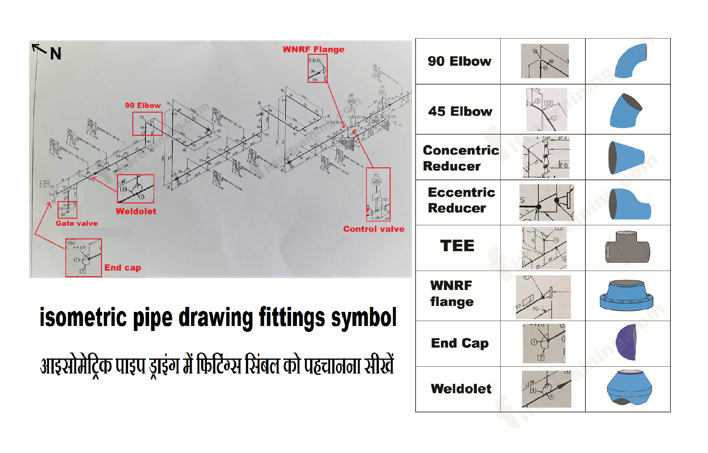
isometric pipe drawing fittings symbol Fitter training

How to read isometric drawing piping dadver

What is Piping Isometric drawing? How to Read Piping Drawing? ALL

Basic Piping Isometric Symbols Piping Analysis YouTube
Piping Isometric Drawing Symbols Pdf at Explore

Piping Isometric Drawing Symbols Pdf at Explore
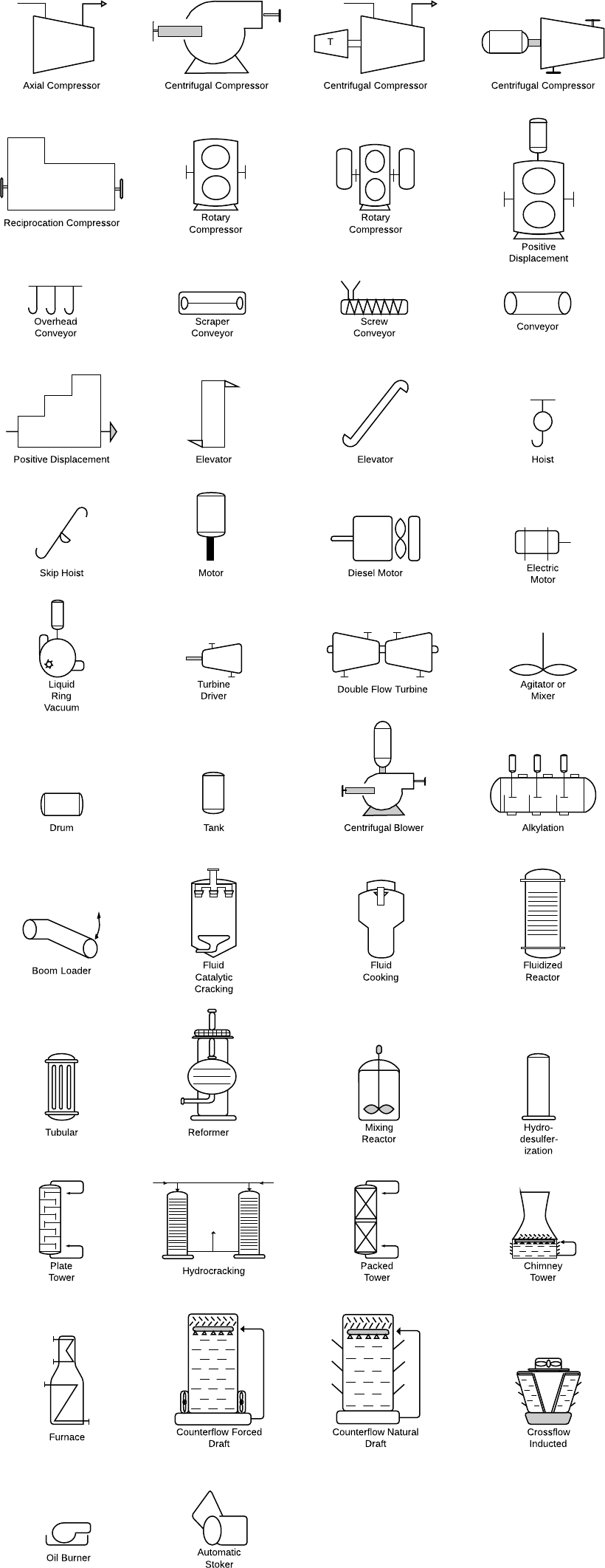
Piping Coordination System Mechanical symbols for Isometric drawings

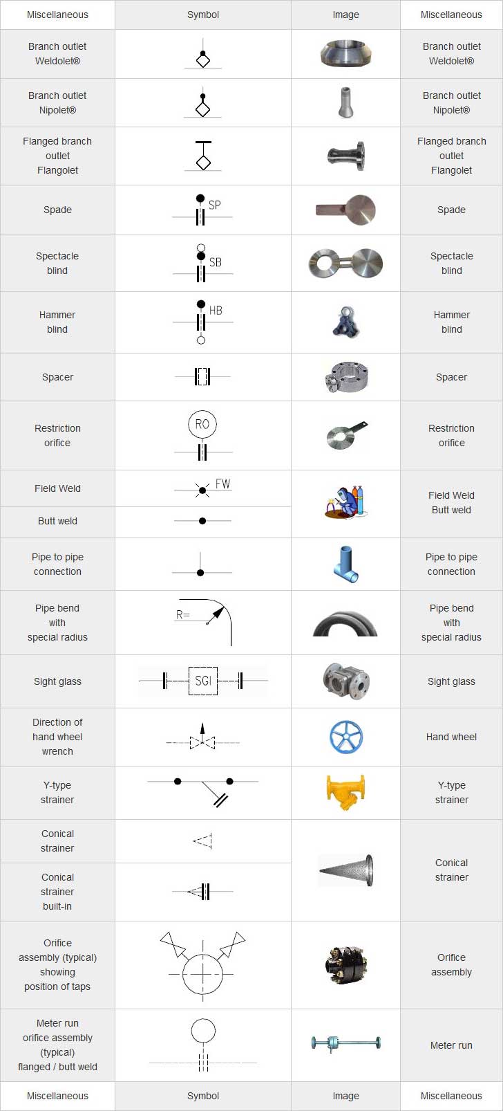
Piping Isometric Drawings The Piping Engineering World
Piping Coordination System Mechanical symbols for Isometric drawings

Piping Isometric DWG Symbols Free Download Drawing in CAD
Web Importance Of Piping Isometrics To The Construction, Commissioning, Safe Operation And Maintenance Of A Process Plant.
They Are Not Realistic, Pipes Are Shown As Single Lines, And Symbols Are Used To Represent Pipe Fittings, Valves, Pipe Gradients, Welds, Etc.
Accurate Drawing Symbols, Callouts, Precise Coordinates, And Elevations Provide Intricate Information To The Fabricator.
Unlike Orthographics, Piping Isometrics Allow The Pipe To Be Drawn In A Manner By Which The Length, Width And Depth Are Shown In A Single View.
Related Post: