How To Draw Bode Plot
How To Draw Bode Plot - Web detailed instructions on how to draw a bode plot diagram on first order denominators and integrators. Web rules for making bode plots. For a simple real pole the piecewise linear asymptotic bode plot for magnitude is at 0 db until the break frequency and then drops. It represents the magnitude response of the system as a function of frequency. Web we draw its intersection with the frequency axis where ω = ωc, since that’s where the magnitude is 0 db. Draw the bode diagram for the transfer function: Web bode plots give engineers a way to visualize the effect of their circuit, in terms of voltage magnitude and phase angle (shift). Web this video illustrates the steps to draw bode plot for a given transfer function and also explains how to find gain margin (gm) and phase margin (pm) and. It is plotted on a logarithmic scale. Make both the lowest order term in the numerator. Draw the line of each individual term on the graph. Make both the lowest order term in the numerator. A bode plot consists of two separate plots, one for. Web we draw its intersection with the frequency axis where ω = ωc, since that’s where the magnitude is 0 db. It is plotted on a logarithmic scale. 12k views 3 years ago pid controllers. Choose the type of bode plot you. Make both the lowest order term in the numerator. Web types of bode plot. For a simple real pole the piecewise linear asymptotic bode plot for magnitude is at 0 db until the break frequency and then drops. The plot displays the magnitude (in db) and phase (in degrees) of the. Web 8 rows draw low frequency asymptote at 0°. Web bode plots give engineers a way to visualize the effect of their circuit, in terms of voltage magnitude and phase angle (shift). This is a quick how to lesson for drawing bode plots. Web rules for making. −40 −20 0 20 40 magnitude (db) 103 104 105 106 107 ω (rad/s). It is plotted on a logarithmic scale. Bode plot for real pole. Procedure to draw bode plot & bode plot for constant kwatch more videos at. Gowthami swarna, tutorials point india private limited. It is plotted on a logarithmic scale. Web get the map of control theory: Choose the type of bode plot you. It represents the magnitude response of the system as a function of frequency. Web we draw its intersection with the frequency axis where ω = ωc, since that’s where the magnitude is 0 db. Web types of bode plot. Draw the bode diagram for the transfer function: Connect with a straight line from 0.1·ω 0 to 10·ω 0. Find the poles and zeros write the transfer function of the circuit in the form h(jw) = a(w) 1 + jw z 1 1 + jw z2 1 +. −40 −20 0 20 40 magnitude (db). Web bode plots give engineers a way to visualize the effect of their circuit, in terms of voltage magnitude and phase angle (shift). Web technique to get started: Web this video illustrates the steps to draw bode plot for a given transfer function and also explains how to find gain margin (gm) and phase margin (pm) and. Select one of. Web 8 rows draw low frequency asymptote at 0°. The plot displays the magnitude (in db) and phase (in degrees) of the. Draw the line of each individual term on the graph. Bode (sys) creates a bode plot of the frequency response of a dynamic system model sys. 12k views 3 years ago pid controllers. 12k views 3 years ago pid controllers. Rewrite the transfer function in proper form. Web in this section we draw the bode plots of each of the indivuidual termas enumerated above. Draw high frequency asymptote at +90°. Make both the lowest order term in the numerator. Select one of the terms by selecting the corresponding radio button. 12k views 3 years ago pid controllers. Find the poles and zeros write the transfer function of the circuit in the form h(jw) = a(w) 1 + jw z 1 1 + jw z2 1 +. Web bode plots give engineers a way to visualize the effect of their. Select one of the terms by selecting the corresponding radio button. Web detailed instructions on how to draw a bode plot diagram on first order denominators and integrators. Web 8 rows draw low frequency asymptote at 0°. Web we draw its intersection with the frequency axis where ω = ωc, since that’s where the magnitude is 0 db. Procedure to draw bode plot & bode plot for constant kwatch more videos at. Draw high frequency asymptote at +90°. A bode plot consists of two separate plots, one for. Find the poles and zeros write the transfer function of the circuit in the form h(jw) = a(w) 1 + jw z 1 1 + jw z2 1 +. It is plotted on a logarithmic scale. Web get the map of control theory: Gowthami swarna, tutorials point india private limited. Web this video illustrates the steps to draw bode plot for a given transfer function and also explains how to find gain margin (gm) and phase margin (pm) and. −40 −20 0 20 40 magnitude (db) 103 104 105 106 107 ω (rad/s). Rewrite the transfer function in proper form. Web bode plots give engineers a way to visualize the effect of their circuit, in terms of voltage magnitude and phase angle (shift). Connect with a straight line from 0.1·ω 0 to 10·ω 0.
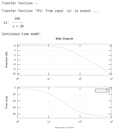
Bode Plot Example Bode Diagram Example MATLAB Electrical Academia

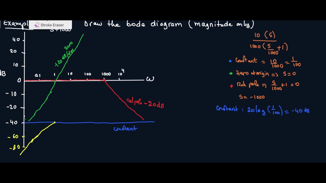
How to draw Bode Plot Solved Example

Bode Plot Example Bode Diagram Example MATLAB Electrical Academia

Drawing Bode Plot From Transfer Function SecondOrder Double Zero

how to draw bode plot in MATLAB Bode plot using MATLAB MATLAB

Drawing Bode Plot From Transfer Function ThirdOrder System Real
How to Draw a Bode Plot (Part 2) YouTube

ME 340 Example Drawing Bode Plot of a Transfer Function 2 YouTube
Bode Plot Matlab How to do Bode Plot Matlab with examples?

Bode Plot EXAMPLE YouTube
Web Rules For Making Bode Plots.
This Is A Quick How To Lesson For Drawing Bode Plots.
Draw The Line Of Each Individual Term On The Graph.
Choose The Type Of Bode Plot You.
Related Post: